The Real Console War Is Thermal
October 19, 2026On March 16, Frore Systems closed a $143 million Series D round at a $1.64 billion valuation. The company does not make games, consoles or graphics cards. It makes cooling hardware, and investors just priced it like a platform company. That should tell you something about where the next round of console and handheld competition is actually happening.
For twenty years the industry sold performance in teraflops. The number went up, the box got faster, everyone moved on. That model is running into a wall made of physics. A modern gaming chip can already do more math than a console can cool. The limit is not how many transistors fit on the die, it is how many watts per square centimetre can leave that die before the silicon cooks itself.
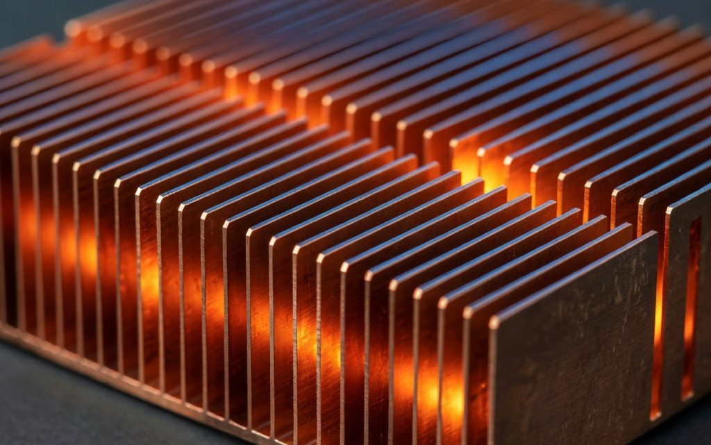
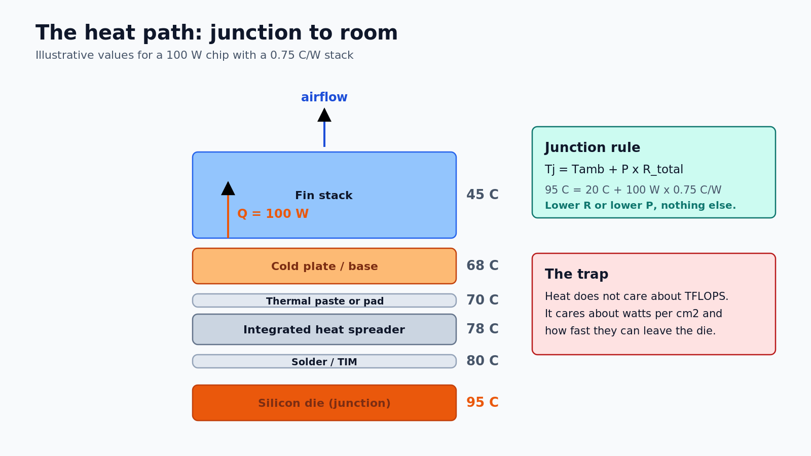
This is the thermal stack: the path from the transistor junction, through solder, heat spreader, cold plate and fins, into the air of your room. Every generation now fights over millimetres and milliwatts inside that path. Understanding it explains why your handheld starts fast and settles slower, why a thin laptop cannot hold a boost clock, and why cooling startups are suddenly worth unicorn money.
A watt is not a degree
Heat is energy. Temperature is a state. A chip can dissipate 100 W and stay at 60 °C if the cooling stack is good, or hit 100 °C at the same 100 W if the stack is bad. The number that connects the two is thermal resistance, measured in degrees Celsius per watt.
The rule is simple enough to fit on a napkin:
Tj = Tamb + P × R_total
Junction temperature equals ambient temperature plus power multiplied by total thermal resistance. For a 100 W chip in a 20 °C room with a 0.75 °C/W stack, the junction sits at 95 °C. That is already close to the limit where firmware starts protecting the silicon.
Resistance adds up in series, exactly like resistors in a circuit. Die to package, package to heat spreader, spreader to cold plate, cold plate to fins, fins to air. The weakest link dominates. A cheap thermal paste with 0.1 °C/W looks irrelevant until you multiply it by 300 W and get 30 °C of drop.
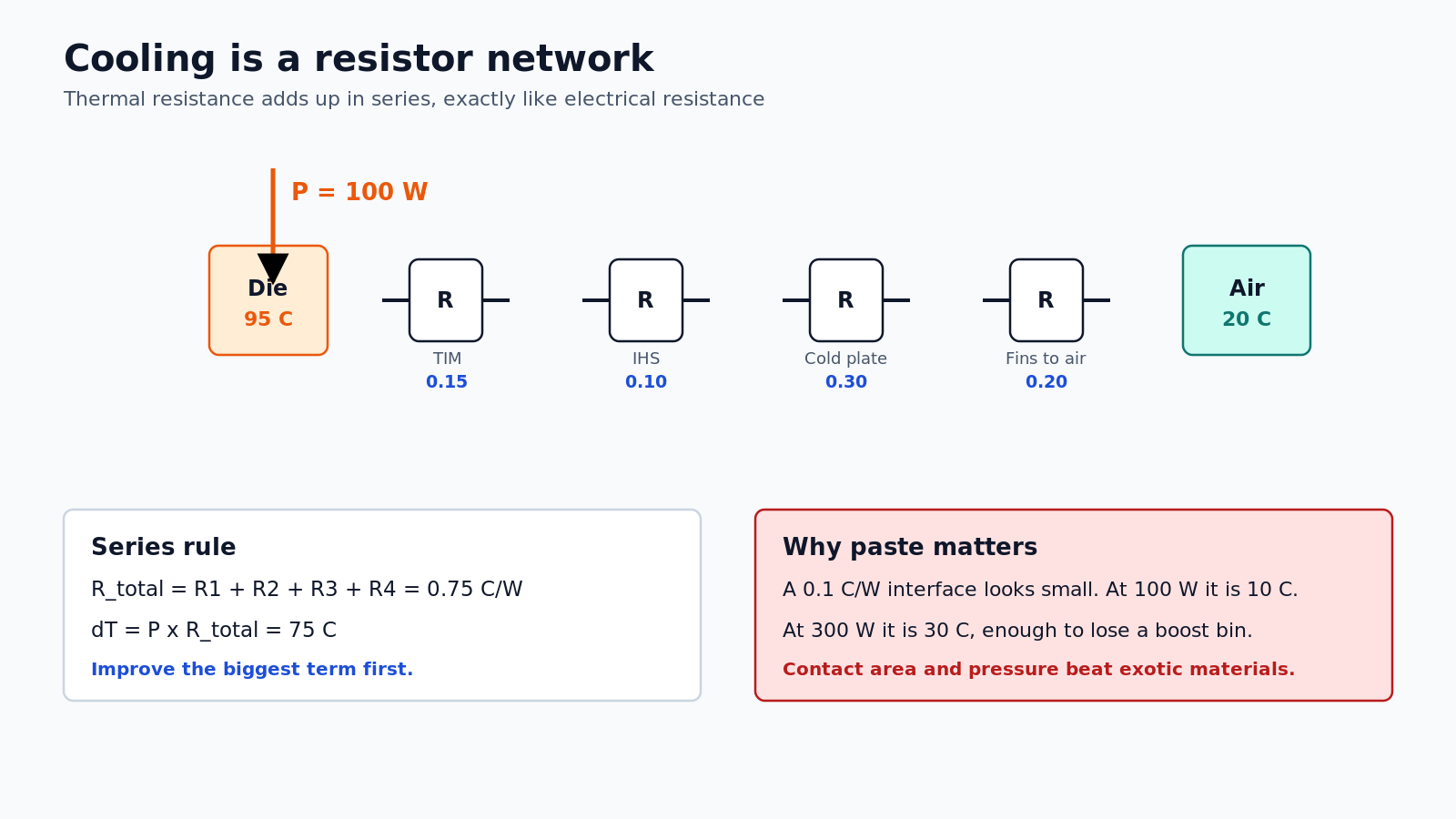
This is why delidding, liquid metal and direct-die cooling exist. They are not exotic for the sake of it. They remove a layer from the network. On a 250 W GPU, removing 0.1 °C/W buys 25 °C of headroom, which the firmware immediately converts into a higher sustained clock.
Why a hot chip is a slow chip
There are three separate mechanisms, and they stack on top of each other.
1. Leakage current rises with temperature
A transistor is never fully off. Subthreshold leakage and gate leakage grow as the junction gets hotter, and in advanced CMOS the leakage power roughly doubles for every 10 °C. That creates a positive feedback loop: hotter chip, more leakage, more power, hotter chip.
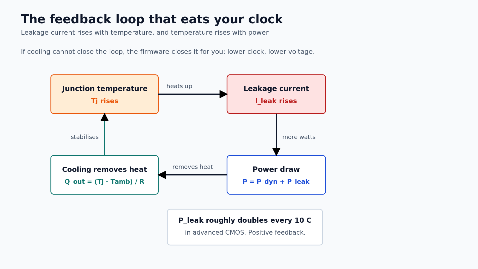
At some point the loop wins. The cooler cannot remove the extra watts, temperature climbs further, and the only remaining brake is firmware. That brake is called DVFS: dynamic voltage and frequency scaling.
2. Frequency costs voltage, and voltage costs power squared
Clock frequency does not scale linearly with voltage. A rough model for a CMOS path is:
f ∝ (V – Vth)^1.3 / V
To get 10 percent more clock, you need roughly 5 to 7 percent more voltage. Dynamic power scales with capacitance times voltage squared times frequency:
P ∝ C × V² × f
Put those together and a 10 percent clock increase costs about 20 to 25 percent more power. The last boost bin is always the most expensive one.
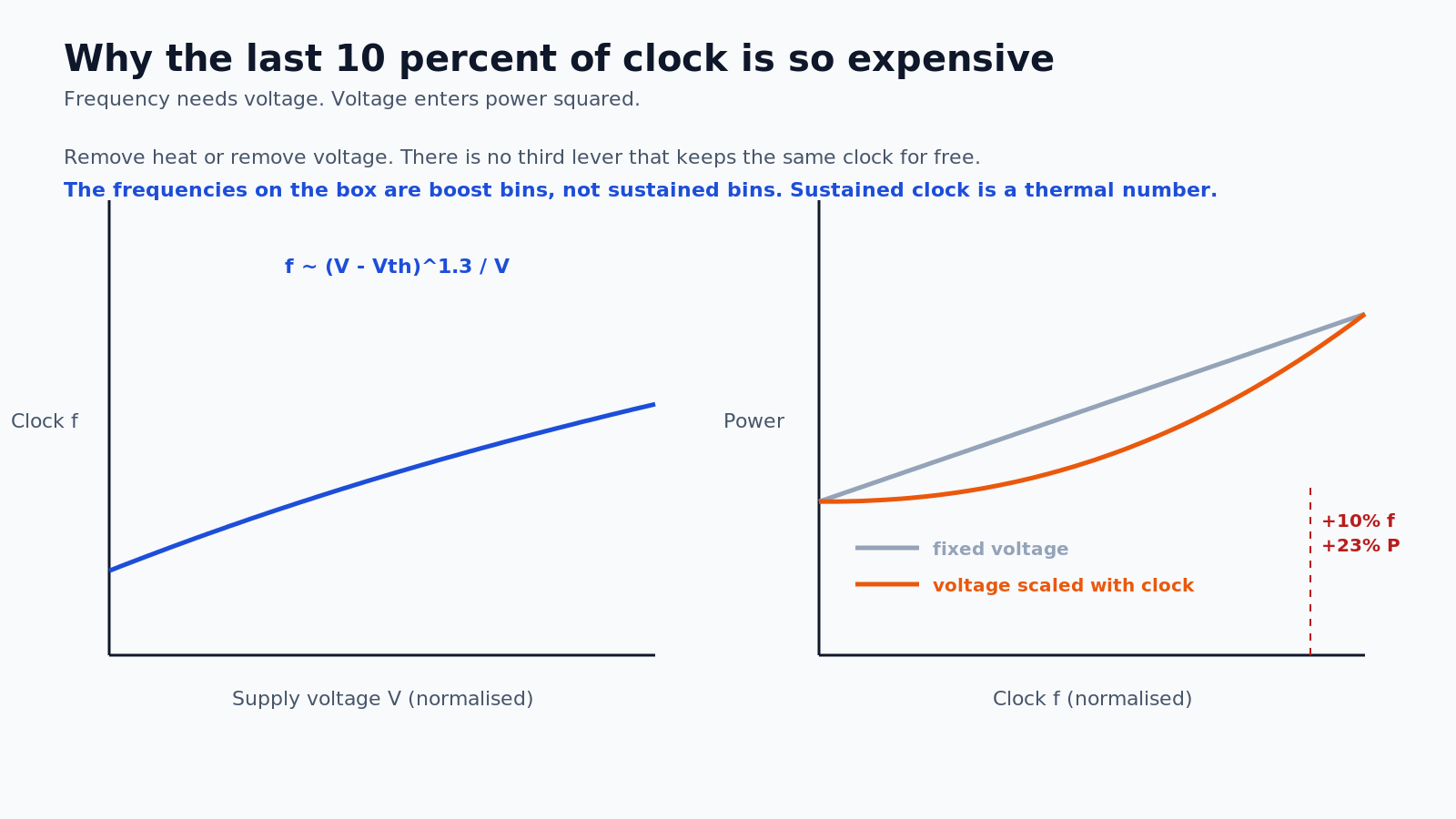
This is why manufacturers ship chips with a wide boost range and a much lower sustained clock. The boost number is real, but it is a capacitor, not a generator. It spends thermal headroom that has to be paid back.
3. Firmware throttles before the silicon dies
Every modern SoC has a thermal budget managed by firmware. It watches junction temperature, package power, current and sometimes skin temperature. When any limit is crossed, it drops frequency and voltage in steps.
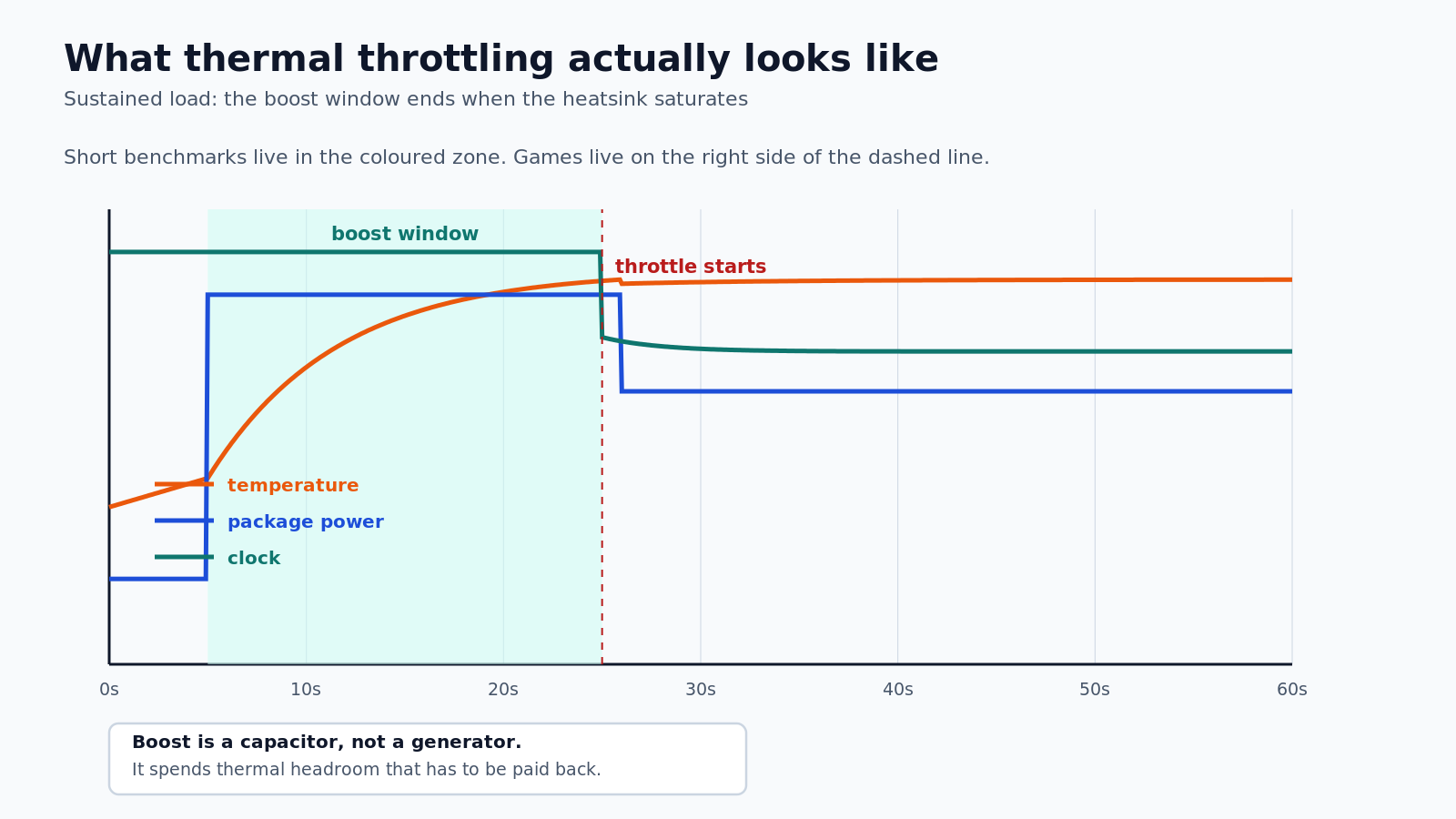
The practical result: a handheld can hit 2.9 GHz for twenty seconds and then settle at 2.2 GHz. Reviewers who measure the first minute report a different console than players who measure the third hour. This is not dishonesty, it is physics with a scheduler.
Average power is a lie
A die is not uniformly hot. CPU cores, GPU clusters, cache and memory controllers have different activity levels, and the hottest block can be several times denser in power than the die average.
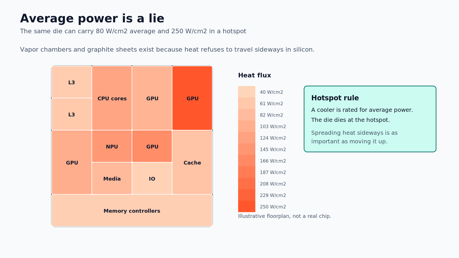
This is why vapor chambers and graphite spreaders matter. Silicon conducts heat poorly sideways, so the job of the spreader is to move heat laterally before it moves vertically. A cooler that only touches the hotspot is a cooler that wastes the rest of its surface.
Junction limits for gaming silicon are typically 95 to 105 °C. Running near that limit is not instantly fatal, but it accelerates electromigration and stresses solder joints. Manufacturers leave margin, and firmware spends that margin as boost.
The cooling ladder
Cooling technologies are easiest to compare by die-level heat flux, the watts per square centimetre they can pull out of the silicon.
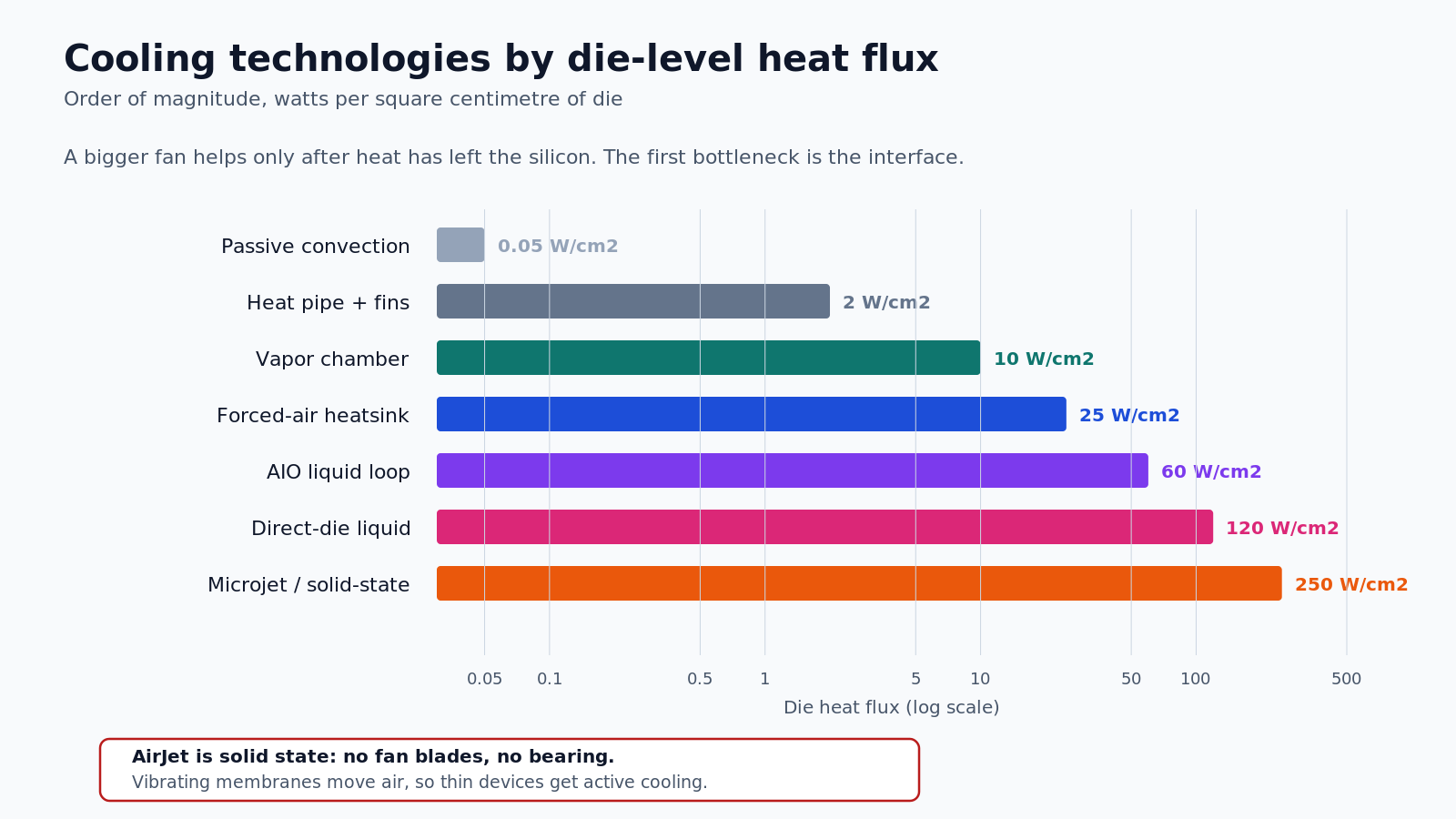
Passive convection handles a fraction of a watt per square centimetre. A heat pipe with fins handles a few watts. A vapor chamber spreads heat across a larger area and pushes the practical limit higher. Forced air with a dense heatsink gets you into the tens. Liquid loops and direct-die cooling go further, and microjet cold plates go further still.
Frore's AirJet is interesting because it is solid state. Instead of a fan blade, vibrating membranes pull air through tiny vents. No bearing, no blade tip noise, and a package thin enough to fit inside a tablet. That is why the company talks about edge AI devices and handhelds, not just data centres.
On the data centre side, Frore claims its LiquidJet cold plate delivers 75 percent higher heat transfer efficiency, 8 °C cooler GPUs, 4 percent more AI tokens per second, 10 percent lower PUE and 55 percent less cold plate weight. Those are vendor numbers and should be treated as such, but the direction is clear: the cooling layer is becoming a product, not an accessory.
Handhelds: a 15 W budget and a 43 °C ceiling
A gaming handheld is the hardest thermal problem in consumer hardware. It has a battery, a screen, radios and a desktop-class SoC inside a plastic shell that a person holds in their hands.
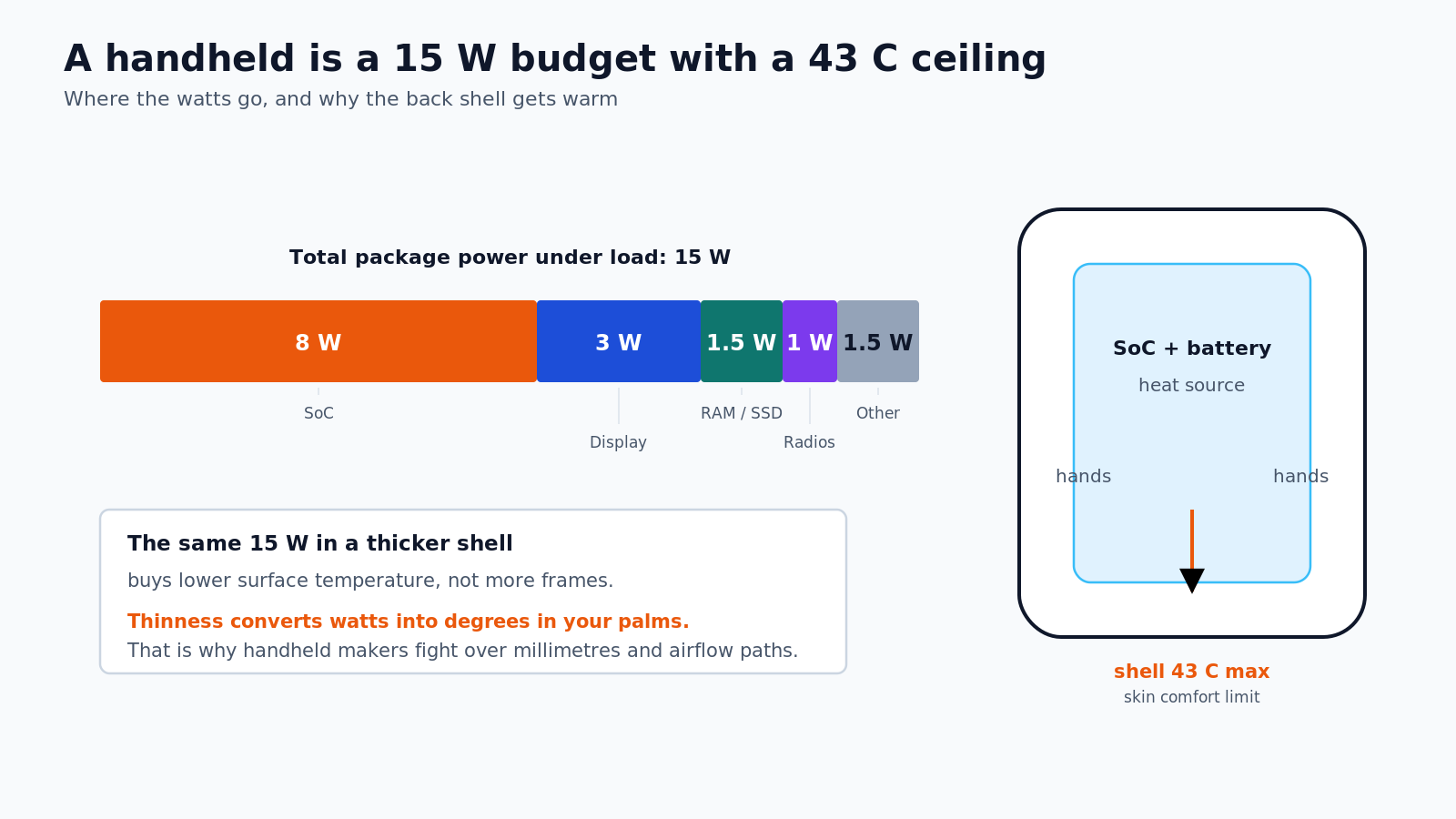
A typical handheld SoC runs at 15 W in its performance mode. The display takes another 3 W, memory and storage about 1.5 W, radios 1 W, and the rest of the board another 1.5 W. The cooling system has to move all of it while keeping the back shell under roughly 43 °C, because that is where the plastic meets a palm.
Thinness makes this worse. A thinner shell means less space for a heatsink, less air volume and a shorter path between the SoC and your hand. This is why handheld makers fight over fan blade design, intake vents and heat pipe routing instead of spending the same effort on a few more compute units.
It also explains the gap between review benchmarks and real sessions. In a 25 °C room on a desk, a handheld can hold its boost clock. In a 30 °C room on a train, with the screen at full brightness and Wi-Fi active, the same device settles lower. The thermal budget did not change. The ambient did.
What consoles are really fighting over
Sony, Microsoft and Nintendo all ship the same basic stack: a large die, a heat spreader, a cold plate, a heatsink and one or two fans. The differences are in how much volume and money they spend on it.
The PlayStation 5 uses liquid metal between the die and the cold plate, which is a direct answer to the resistance problem. The Xbox Series X uses a vapor chamber and a large axial fan, which is an answer to the spreading problem. Nintendo's handheld line lives on the other end of the curve, where every millimetre and every watt of display power matters.
The next generation will not be decided by a teraflop headline. It will be decided by how long a box can hold its clock in a normal room, how loud it gets while doing it, and how much of the bill goes to the thermal stack instead of the die. That is the boring, expensive, physical part of the console war, and it is now the part investors are paying for.
What to look for when you buy
- A vapor chamber or a large cold plate, not just a bigger fan. The bottleneck is usually the interface, not the airflow.
- Two fans with independent curves beat one loud fan. Noise is a thermal budget too.
- A performance mode that is sustained, not a boost number measured for thirty seconds. Look for third-party tests that run for at least thirty minutes.
- Inlet and exhaust clearance. A handheld on a blanket is a handheld with a smaller cooler.
- Dust. Every millimetre of dust on a fin stack is extra thermal resistance, and it compounds over a year.
The next war is measured in millimetres
For a decade the industry optimized the transistor. The transistor got good enough that the package, the paste, the spreader and the fan became the limiting factors. Frore's valuation is a bet that this continues, and that the companies who own the thermal stack will capture a meaningful part of the performance gains.
For gamers, the practical lesson is simpler. When a new handheld or console is announced, ignore the peak clock for a moment. Ask what the sustained clock is, how loud the device is at that clock, and how warm the shell gets. Those three numbers describe the real machine. Everything else is a boost window.
The next console war will not be won in teraflops. It will be won in millimetres and milliwatts, one layer of thermal resistance at a time.